



Key Takeaways
- Choose the machining strategy based on part complexity: 3-axis machining works well for straightforward parts, while 3+2 and 5-axis machining provide greater flexibility for complex geometries and features that require access from multiple angles.
- 3+2 machining can reduce setups without abandoning familiar 3-axis strategies: Creo uses the additional rotational axes to reposition the tool, allowing shops to machine multiple sides of a component with fewer manual setups.
- Creo connects design directly to manufacturing: Integrated NC machining and tool path creation let teams build machining sequences from the actual part geometry, helping keep manufacturing aligned with the engineering definition.
- Fewer setups can mean faster, more accurate production: Using the right combination of 3-axis, 3+2, and 5-axis capabilities can reduce handling, limit alignment errors, improve machining accuracy, and shorten the path from design to finished part.
Choosing the right machining strategy can have a major impact on production speed, accuracy, and part quality for manufacturers, especially those working with increasingly complex parts. While traditional 3-axis machining remains effective for many applications, 5-axis capabilities give manufacturers greater flexibility when producing complex geometries or machining multiple sides of a component. Creo Parametric helps bridge design and manufacturing by providing integrated numerical control (NC) machining and toolpath creation capabilities. Engineers can create machining sequences directly from part geometry, simulate material removal, and validate tool movement before the job reaches the machine. For high-performance shops, understanding when to use 3-axis, 3+2, or full 5-axis machining can help reduce setups, improve accuracy, and accelerate production.

What Is the Difference Between 3-Axis and 5-Axis Machining in Creo?
3-axis machining controls the cutting tool along the X, Y, and Z axes. Engineers commonly use it for flat features, pockets, volume roughing, and standard surface finishing. The tool approaches the workpiece from a fixed orientation, making 3-axis machining generally simpler to program and highly efficient when the necessary features are accessible from one direction. The challenge comes when a part has features on multiple sides or contains more complex geometry. Manufacturers may have to reposition or flip the part between operations. Each additional setup adds handling time and introduces another opportunity for alignment errors.
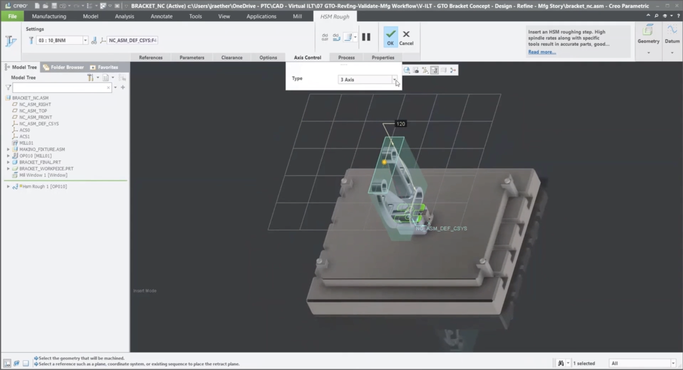
5-axis machining adds two rotational axes, allowing the cutting tool or workpiece to approach geometry from additional angles. This is especially valuable for complex aerospace components, deep cavities, curved surfaces, molds, and other parts that are difficult to machine from a single orientation. Creo supports both simultaneous 5-axis machining and 3+2 machining, sometimes called positional 5-axis machining.
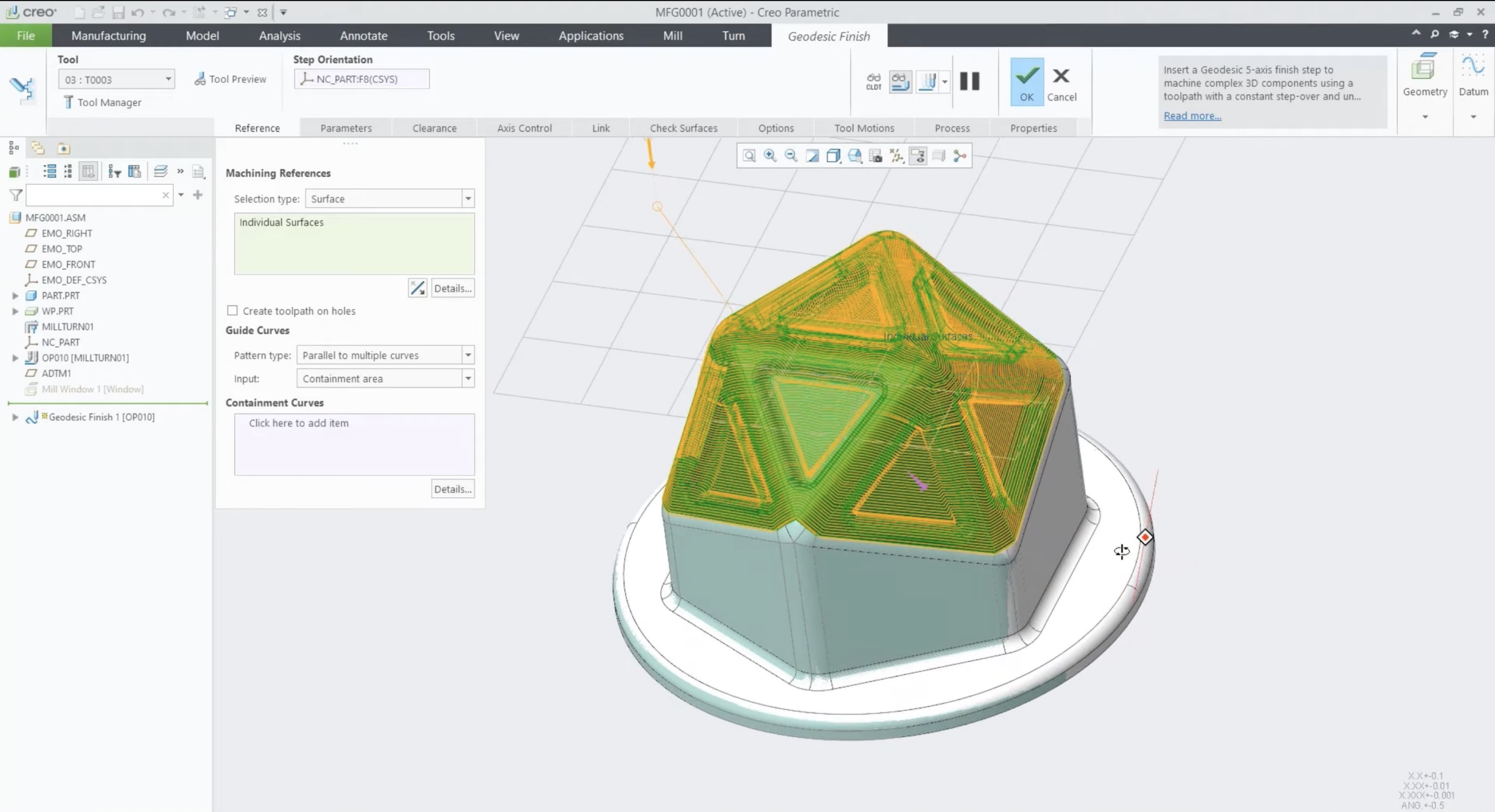
With 3+2 machining, the fourth and fifth axes reposition the cutting tool at a fixed angle. Once positioned, the machine performs a traditional 3-axis cutting operation. This allows manufacturers to reach multiple sides of a component without manually repositioning the workpiece. Creo can create a single toolpath that combines 3-axis machining with plus-two positioning, helping shops reduce setups while maintaining familiar 3-axis cutting strategies.
Example: Creating a 3+2 Machining Sequence in Creo
A typical Creo manufacturing workflow starts by defining the material that needs to be removed.
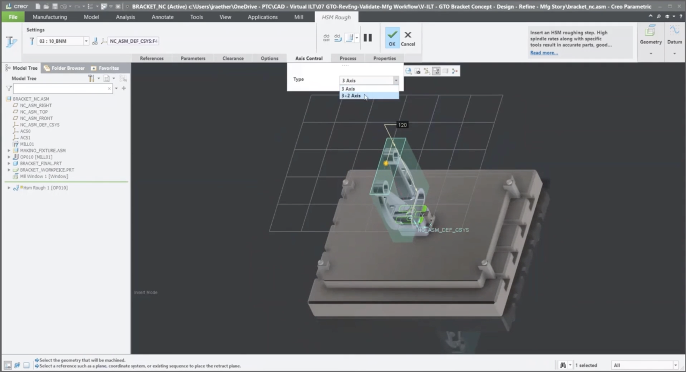
First, the user creates a mill window that identifies the volume of material to machine. The initial roughing toolpath can then be created by specifying the mill window, cutting tool, machining parameters, tool clearance settings, and access controls. For a 3+2 operation, the user selects 3+2 axis control. Creo then uses the additional rotational axes to position the tool so material can be machined from different directions.
Once the NC sequence has been defined, Creo provides several ways to validate the operation before machining begins. The Play Path option lets the user visualize the trajectory of the cutting tool. Manufacturers can also run a material removal simulation to see how the tool interacts with the stock throughout the operation.
This simulation is particularly important for more advanced machining strategies. Creo can help identify potential:
- Collisions, where the cutting tool unintentionally contacts the fixture
- Gouges, where the cutting tool removes material from an area of the finished part that should remain untouched
After the initial roughing sequence is complete, manufacturers can add additional roughing operations using smaller tools to reach areas that were inaccessible during the first pass. Finishing sequences are then created to remove the remaining stock and produce the final geometry. Creo machining sequences directly reference the underlying part geometry, resulting in toolpaths that remain closely connected to the product’s engineering definition.
3-Axis or 5-Axis Machining for Your Team?
The choice between 3-axis and 5-axis machining is not simply about selecting the most advanced machine available. For straightforward parts that can be accessed from a single orientation, 3-axis machining can provide an efficient and cost-effective approach. For complex components requiring access from multiple angles, 3+2 or simultaneous 5-axis machining can reduce setups, improve tool access, and support more sophisticated geometries. Creo gives manufacturers the ability to bring these machining strategies into the same design and manufacturing environment. With integrated tool path creation, material removal simulation, collision detection, and gouge checking, teams can validate manufacturing processes before production begins.
For high-performance manufacturing shops, that connection between design and machining can mean fewer surprises on the shop floor, greater machining accuracy, and a faster path from finished design to finished part. If you would like to discuss Creo’s features further, let’s have a conversation.